When the outlet velocities during the design-year storm event are 5 ft/s or greater, the PEO shall use an energy dissipator. Energy dissipators can be quite simple or very complex, depending on site conditions. Debris and maintenance problems should be considered when designing energy dissipators.
Energy dissipators include:
• Rock-protected outlets
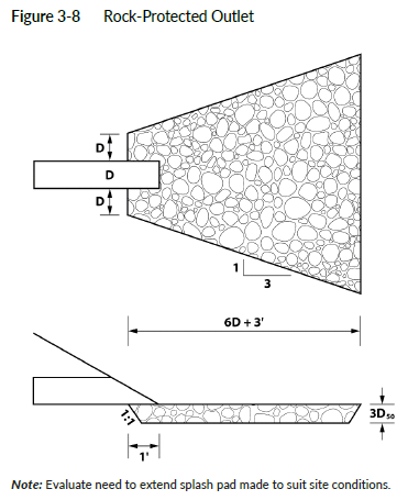
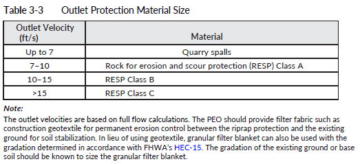
Rock is frequently hand placed around the outlet end of culverts to protect against the erosive action of the water (Figure 3-8). The material size at the outlet is dependent on the outlet velocity as determined using a full flow analysis as noted in Table 3-3. The limits of this protection would cover an area that would be vulnerable to scour holes. As an alternative to using Figure 3-8 and Table 3-3, the Hydraulic Toolbox calculator, which can be downloaded from FHWA’s website, can be used to determine the area of the scour protection and the size of the riprap. Refer to Table 4-2 for the class of rock or riprap to be used. The calculation results need to be included in the Hydraulic Report. (See Section 3-4.5 for details on wing walls and aprons.)
• Other energy-dissipating structures
Other structures include impact basins and stilling basins/wells designed according to the FHWA’s HEC-14, “Hydraulic Design of Energy Dissipators for Culverts and Channels.” These structures may consist of baffles, posts, or other means of creating roughness to dissipate excessive velocity. The State Hydraulics Office shall be consulted to assist in the design of these types of structures.
Energy dissipators have a reputation for collecting debris on the baffles, so the PEO should consider this possibility when choosing a dissipator design. In areas of high debris, the dissipator should be kept open and easily accessible to maintenance crews. Provisions should be made to allow water to overtop without causing excessive damage.