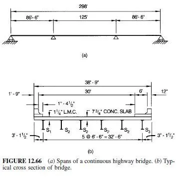
Specifications of the American Association of State Highway and Transportation Officials (AASHTO) require that the width of a bridge roadway between curbs be divided into design traffic lanes 12 ft wide and loads located to produce maximum stress in supporting members. (Fractional parts of design lanes are not used.) Roadway widths from 20 to 24 ft, however, should have two design lanes, each equal to one-half the roadway width. Truck and lane loadings are assumed to occupy a width of 10 ft placed anywhere within the design lane to produce maximum effect.
If curbs, railings, and wearing surfaces are placed after the concrete deck has gained sufficient strength, their weight may be distributed equally to all stringers or beams. Otherwise, the dead load on the outside stringer or beam is the portion of the slab it carries.
The strength and stiffness of the deck determine, to some extent, the distribution of the live load to the supporting framing.
Shear. For determining end shears and reactions, the deck may be assumed to act as a simple span between beams for lateral distribution of the wheel load. For shear elsewhere, the wheel load should be distributed by the method required for bending moment.
Moments in Longitudinal Beams. For ASD and LRFD, the fraction of a wheel load listed in Table 11.14 should be applied to each interior longitudinal beam for computation of liveload bending moments.
For an outer longitudinal beam, the live-load bending moments should be determined with the reaction of the wheel load when the deck is assumed to act as a simple span between beams. When four or more longitudinal beams carry a concrete deck, the fraction of a wheel load carried by an outer beam should be at least S/ 5.5 when the distance between that beam and the adjacent interior beam S, ft, is 6 or less. For 6 14, no minimum need be observed.


Moments in Transverse Beams. When a deck is supported directly on floorbeams, without stringers, each beam should receive the fraction of a wheel load listed in Table 11.15, as a concentrated load, for computation of live-load bending moments.
Distribution for LRFD. Research has led to recommendations for changes in the distribution factors DF in Tables 11.14 and 11.15. AASHTO has adopted these recommendations as the basis for an approximate method in the LRFD Specifications, when a bridge meets specified requirements. As an alternative, a more refined method such as finite-element analysis is permitted.


Eq. 11.10 and 11.11 apply only for spans from 20 ft to 240 ft with 4-1â„2 to 12 in thick concrete decks (or concrete filled, or partially filled, steel grid decks), on four or more steel girders spaced between 3.5 ft and 16.0 ft. The multiple presence factors, m, in Table 11.2 are not to be used when this approximate method of load distribution is used. For girder spacing outside the above limits, the live load on each beam is determined by the lever rule (summing moments about one support to find the reaction at another support by assuming the supported component is hinged at interior supports). When more refined methods of analysis are used, the LRFD Specification states that a table of live load distribution coefficients for extreme force effects in each span shall be provided in the contract documents to aid in permit issuance and rating of the bridge.


