A composite beam is usually designed first for ultimate limit states. Its behaviour in service must then be checked. For a simply-supported beam, the most critical serviceability limit state is usually excessive deflection, which can govern the design where unpropped construction us used. Floor structures subjected to dynamic loading (e.g. as in a gymnasium) are also susceptible to excessive vibration (Section 3.11.3.2).
Cracking of concrete is a problem only in fully-encased beams. Which are rarely used, and in hogging regions of continuous beams (Section 4.2.5).
Some codes of practice limit stresses in service; but excessive stress is not itself a limit state. It may however invalidate a method of analysis (e.g.linear0elastic theory) that would otherwise be suitable for checking compliance with a serviceability criterion. No stress limits are specified in Eurocode 4; Part 1.1. The policy is to use elastic analysis, allowing for shear lag and creep; and to modify the results, where necessary, to allow for yielding of steel and, where partial shear connection is used, for excessive slip.
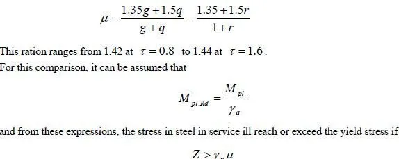
If yielding of structural steel occurs in service, in a typical composite beam for a building, it will be in the bottom flange, near midspan. The likelihood of this depends on the ratio between the characteristic variable and permanent loads, given by
where My is the bending moment at which yield of steel first occurs. For sagging bending, it is typically between 1.25 and 1.35 for propped construction, but can rise to 1.45 or above, for unpropped construction.
Deflections are usually checked for the rare combination of actions, given in equation (1.8). So for a beam designed for distributed loads gk and qk only, the ratio of design bending moments (ultimate/serviceability) is

The values given above show that this is unlikely for propped construction, but might occur for unpropped construction when a γ for structural steel is assumed to be 1.05 or less, rather than 1.10 as recommended in Eurocode 4.
Where the bending resistance of a composite section is governed by local buckling, as in c Class 3 section, elastic section analysis is used for ultimate limit states, and then stresses and/or deflections in service are less likely to influence design.
As shown below, elastic analysis of a composite section is more complex than plastic analysis, because account has to be taken of the method of construction and of the effects of creep. The following three types of loading then have to be considered separately:
load carried by the steel beam, short-term load carried by the composite beam long-term load carried by the composite beam
3.7.1 Elastic analysis of composite sections in sagging bending
It is assumed first that full shear connection is provided, so that the effect of slip can be neglected.
All other assumptions are as for the elastic analysis of reinforced concrete sections by the method of transformed sections. The algebra is different because the flexural rigidity of the steel section alone is so much greater than that of reinforcing bars.
For generality, the steel section is assumed to be asymmetrical (Fig.3.25) with cross-sectional area Aa, second moment of area Ia, and centre of area distance zs below the top surface of the concrete slab, which is of uniform overall thickness ht and effective width beff.
The modular ratio for short-term loading is
n= Ea / Ec
where the subscripts a and c refer to structural steel and concrete, respectively. For long-term loading, a value n/3 is a good approximation. For simplicity, a single value n/2 is sometimes used for both types of loading. From here onwards, the symbol n is used for whatever modular ration is appropriate, so it is defined by
n= Ea / E’c
where E’c
E is the relevant effective modulus for the concrete.
It is usual to neglect reinforcement in compression, concrete in tension, and also concrete between the ribs of profiled sheeting, even when the sheeting spans longitudinally. The condition for the neutral-axis depth x to be less than he is
In global analyses, it is sometimes convenient to use values of I based on the uncracked composite section. The values of x and I are then given by equations (3.88) and (3.89) above, whether x exceeds hc or not. In sagging bending, the difference between the cracked and uncracked values of I is usually small.
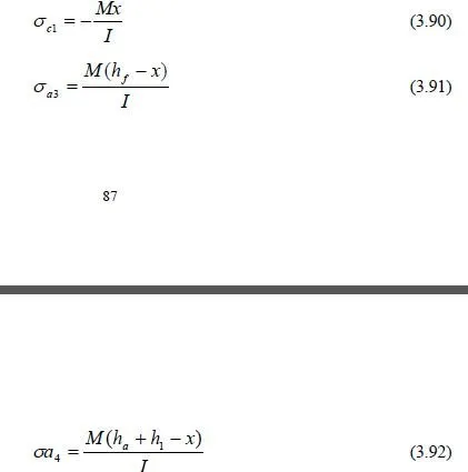
Stresses due to a sagging bending moment M are normally calculated in concrete only at level I in Fig.3.25, and in steel at levels 3 and 4. these stresses are, with tensile stress positive:


