Bond
Until the use of deformed bars became common, most of the reinforcement for concrete consisted of smooth mild-steel bars. The transfer of shear from steel to concrete was assumed to occur by bond or adhesion at the concrete-steel interface. Where the steel component of a composite member is surrounded by reinforced concrete, as in an encased beam, Fig.2.1(c), or an encased stanchion, Fig, 5.15, the analogy with reinforced concrete suggests that no shear connectors need be provided. Tests have shown that this is usually true for cased stanchions and filled tubes, where bond stresses are low, and also for cased beams in the elastic range. But in design it is necessary to
restrict bond stress to a low value, to provide a margin for the incalculable of steel surfaces, and stresses due to variations of temperature.
Research on the ultimate strength of cased beam(1-9) has shown that at high loads, calculated bond stresses have little meaning, due to the development of cracking and local bond failures If longitudinal shear failure occurs, it is invariably on a surface such as AA in Fig .2.1(c), and not around the perimeter of the steel section. For these reasons, British codes of practice do not allow ultimate-strength design methods to be used for composite beams without shear connectors.
Most composite beams have cross-sections of types (a) or (b) in Fig. 2.1.Tests on such beams show that at low loads, most of the longitudinal shear is transferred by bond at the interface, that bond breaks down at higher loads, and that bond at the interface, that bond breaks dows at higher loads, and that once broken it cannot be restored. So in design calculations, bond strength is taken as zero, and in research, bond is deliberately destroyed by greasing the steel flange before the connection is some form of dowel welded to the top flange of the steel member and subsequently surrounded by in-situ concrete when the floor or deck slab is cast.
Shear connectors
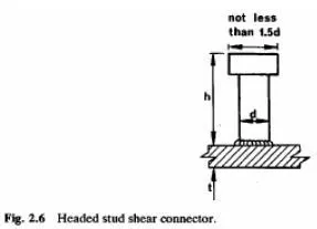
The most widely used type of connector is the headed stud (Fig.2.6).These range in diameter from 13 to 25 mm. and in length (h) from 65 to 100 mm, though longer studs are sometimes used. The current British code of practice (14) requires the steel from which the studs are manufactured to have an ultimate tensile strength of at least 450 N/mm2 and an elongation of at least 15% The advantages of stud connectors are that the welding process is rapid, they provide little obstruction to reinforcement in the concrete slab, and they are equally strong and stiff in shear in all directions normal to the axis of the stud.

There are two factors that influence the diameter of studs One is the welding process, which becomes increasingly difficult and expensive at diameters exceeding r20mm, and the other is the thickness, (Fig.2.6) of the plate of flange to which the stud is welded. A study made in the USA(20) found that the full static strength of the stud can be developed if dit is less than about 2.7, and a limit of 2.5 is given in Eurocode 4. Tests using repeated loading (21)led to the rule in the British bridge code(22)that where the flange plate is subjected to fluctuating tensile stress, dit may not Exceed 1.5; these rules prevent the use of welded studs as shear connection in composite slabs.
The maximum shear force that can be resisted by a stud is relatively low, about 150 kN. Other types of connector with higher strength have been developed. Primarily for use in bridges There are bars with hoops (Fig 2.7(a)).tees with hoops, horseshoes, and channels (Fig.2.7(b)).Bars with hoops are the strongest of these, with ultimate shear strengths up to 1000 kN. Eurocode 4 also gives design rules for block connectors. Anchors made from reinforcing bars ,angle connectors and friction-grip bolts made from reinforcing bars, angle connectors and friction-grip bolts ,Epoxy
adhesives have been tried but it is not clear how resistance to uplift can reliably be provided where
the slab is attached to the steel member only at its lower surface.

Shear connection for profiled steel sheeting
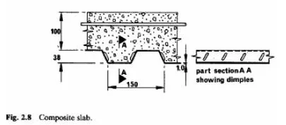
This material is commonly used as permanent formwork for floor slabs in connectors to material that may be less than 1mm thick, shear connection is provided either by provided either by pressed or rolled diples that project into the concrete, or by giving the steel profile a re-entrant shape that prevents separation of the steel from the concrete.
The resistance of composite slabs to longitudinal shear is covered in section 2.8 and their design section 3.3
