Because of local buckling, the ability of a steel flange or web to resist compression depends on its slenderness, represent by its breadth/thickness ration. In design to Eurocode 4, as in Eurocode 3, each flange or web in compression is placed in one of four classes. The highest (least slender) class is Class 1(plastic). The class of a cross-section of a composite beam is the lower of the classes of its web and compression flange, and this class determines the design procedures that are available.
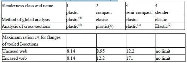
This well-established system is summarized in Table 3.1. The Eurocodes allow several methods of plastic global analysis, of which rigid-plastic analysis (plastic hinge analysis) is the simplest. This is considered further in Section 4.3.3.
The Eurocodes give several idealized stress-strain curves for use in plastic section analysis, of which only the simplest (rectangular stress blocks) are use in this volume.
Table 3.1 Classification of sections, and methods of analysis.
Notes: (1) bole in the web method enables plastic analysis to be used;
(2) with reduced effective width of yield strength;
(3) for Grsde 50 steel (fy-355N/mm2), c is half the width of a flange of thickness
(4) elastic analysis may be used, but is more conservative.
The class boundaries are defined by limiting slenderness ration that are proportional to (fy)-0.5, where fy is the nominal yield strength of the steel. This allows for the influence of yielding on loss of resistance during buckling. The ratios is Eurocode 4; Part 1.1 for steel with fy=355N/mm2 are given in Table 3.1 for uniformly compressed flanges of rolled 1-sections, of overall width 2c.
Encasement of webs in concrete, illustrated in Fig.3.31, is done primarily to improve resistance to fire (Section 3.10). It also prevents rotation of a flange towards the web, which occurs during local buckling, and so enables higher c/t rations to be used at the class 2/3 and 3/4 boundaries, as shown.
At the higher compressive strains that are relied on in plastic hinge analysis, the encasement is weakened by crushing of concrete, so the c/t ration at the class 1/2 boundary is unchanged.
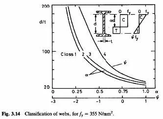
The class of a steel web is strongly influenced by the proportion of its clear depth, d, that is in compression, as shown in Fig.3.14. For the class 1/2 and 2/3 boundaries, plastic stress blocks are used, and the limiting d/t ratios are given in Eurocodes 3 and 4 as functions of α , defined in Fig.3.14. the curves show, for example, that a web with d/t=40 moves from Class 1 to Class 3 when α increases from 0.7 to 0.8. This high rate of change is significant in the design of continuous beams (Section 4.2.1).
For the class 3/4 boundary, elastic stress distributions are used, defined by the ration ψ = −1.
The elastic neutral axis is normally higher, in a composite T-beam, than the plastic neutral axis, and its position for propped and unpropped construction are different, so the curve for the class 3/4 boundary is not comparable with the others in Fig.3.41.

For simply-supported composite beams, the steel compression flange is restrained from local bucking (and also from lateral buckling) by its connection to the concrete slab, and so is in Class 1. The plastic neutral axis for full interaction is usually within the slab or steel top flange, so the web is not in compression, when flexural failure occurs, unless partial shear connection (Section 3.5.3.1) is used. Even then, α us sufficiently small for the web to be in Class 1 or 2. (This may not be so for the much deeper plate or box girders used in bridges.)
During construction of a composite beam, the steel beam alone may be in a lower slenderness class than the completed composite beam, and may be susceptible to lateral buckling. Design for this situation is governed by a code for steel structures (e.g. Eurocode 3).
